|
|
Post by VBF-12 Gosling on Feb 27, 2019 13:18:35 GMT -5
Gents The main combat system of the F-18 is its very capable radar. This series of posts intends to go over this system in steps to build a thorough knowledge of the radar and how to use it. Like the Navigation Systems posts I hope to build this into a sequence of related posts with the link index below. Some of the entries may be initially out of sequence but I will rearrange them in the future to build knowledge of the system in a coherent way. Posts yet to be completed are in ItalicsTHE APG-73 RADARRadar System LinksR01 - OverviewR02 - Operation Theory and TerminologyR03 - DDI SymbologyR04 - Air / Air ModesR05 - Display InterpretationR06 - Controls and Interaction
R07 - .... Stuff I haven’t thought of .....
R08 - New features and modesAs new features are developed and introduced these posts will be modified and further posts added to coverthe new features. These posts are largely based on Redkite’s Radar Tutorial Youtube Video on the subject for which I an very grateful. |
|
|
|
Post by VBF-12 Gosling on Feb 27, 2019 13:43:44 GMT -5
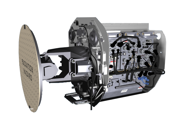
R01 - OVERVIEWDescriptionThe AN/APG-73 Radar is an all-digital, X-Band multimode radar for use in both air-to-air and air-to-ground combat missions. It is an all weather, coherent, multimode, multi-waveform search-and-track sensor. Over it’s predecessors it has increased memory, bandwith, frequency agility, and higher analogue/digital sampling rates. Advanced technology has provided the system with much better electronic counter-countermeasures, mainly through flexible software in the processors which allow the radar to adapt quickly to different threats. Faster analogue-to-digital conversion improves the radar resolution cell and the new signal processor improves doppler resolution. This enables better discrimination between closely-spaced targets.  Features FeaturesThe AN/APG-73 Air-to-Air Radar has the following features currently implemented: - Pulse-Doppler
- Look-down / Shoot-down
- BVR - Beyond Visual Range modes:
- RWS - Range While Scan
- STT - Single Target Track
[li]ACM - Air Combat Maneuvering mode[/li] [/ul] Further modes will be added as updates are implemented. These will hopefully include: - LTWS - Latent Track While Scan will overcomes the limitation of being unable to see the other targets once a target has been locked
- LDF - Low Doppler Filter allows slow moving targets (eg ground vehicles etc) to be filters out
- ECCM - Electronic Counter Counter Measures combats enemy radar jamming and allows the F-18 to “burn through” enemy jamming better, however there is a commensurate drop off in radar detection capability as a result
- MSI - Multi Sensor Integration - Allows tracks received via the datalink, RWR and FLIR in due course to be displayed on the radar
- RAID 1LOOK - I beleive this is a Raid Assessment mode that helps identify if a contact is actually a cluster of contacts
Full features or the real radar:Air-to-air modes: - Velocity search (high PRF) - Range-while-search (high/medium PRF) - Track-while-scan (maintains 10, displays 8) - Short-range automatic acquisition - Gun acquisition - Vertical scan acquisition - Boresight acquisition - Wide-angle acquisition - Single target track - Gun director - Helmet Mounted Cueing Air-to-surface modes: - Real beam ground map - Radar navigation ground map - Doppler beam sharpened sector - Doppler beam sharpened patch - Medium-resolution synthetic aperture radar - Fixed target track - Ground moving target indication/track - Sea surface search - Air-to-surface ranging - Terrain avoidance - Precision velocity update - Inverse range angle The first post on the ED Forums for the Radar gives a lot of basic information. Link Here. Also, there is a huge and very informative post on the VR Simulations forum here.
|
|
|
|
Post by VBF-12 Gosling on Mar 13, 2019 15:47:35 GMT -5
R02 - OPERATION THEORY AND TERMINOLOGYRef: Radar Theroy T-45CI’ll try not to be too easy with this as you all know that it’s radio energy transmitted in a beam and the detection of the reflected radio energy. Azimuth ResolutionTo be able to identify two contact at the same range we need a narrow horizontal beam. Making the beam narrow limits the energy we can put out, so its a balance. As range reduces then Azimuth Resolution improves. Range ResolutionTo “see” a long way with the radar we need to wait longer for the radar returns to come back so the time between pulses has to be long enough fo the energy to get out there and back. However, the longer we wait the lower the Pulse Repartition Frequency and so the less accurate the range updates. Also, as range increases the energy arriving at the target is reduce as it is spreading out both horizontally and vertically (Inverse Square Law). So less energy hits the target. Target Radar SignatureThe reflected energy also suffers from Inverse Square Law on the way back so we receive only a small amount of the transmitted energy. We need a really powerful transmitter and a very sensitive receiver. Needless to say the enemy aircraft is likely to know we are transmitting well beyond the range where we get a reflection from him. This is one of the main reasons for the development of the Gen5 fighters - F-22, F-35 etc - The much smaller forward radar reflection aim to result in them not appearing on the opposition radar until after they are within own launch parameters) Types of Radar TransmissionRadar has developed from just a single pulse to being complex wave forms that provide much more information about the target than just its range and bearing. The types are: - Pulse - Basic Radar pulse providing slant range and azimuth bearing
- Pulse-Doppler – Transmission and reception are similar to the Pulse system, but the PD system distinguishes contacts by the frequency shift of the echo rather than the time between pulses
- Continuous Wave - Uses a continuous transmission from one antenna, while using a separate antenna to receive the returned echo. Very accurate azimuth and elevation measurements. Missile guidance and Fire Control - It is often the indicator of a Lock
- Pulse-Doppler - This works from the principle of frequency shift known as Doppler Effect. This effect is the observed change in frequency of a wave for an observer moving relative to the source. If the frequency received is higher than transmitted the target is closing, lower it is reseeding. This frequency shift when combined with our own speed is used to accurately determine the velocity of a target
AntennaTHe type of antenna greatly affects the radar performance. The types are: - Omni Directional - Radiates through 360 degrees - Comms radio antenna
- Parabolic - Focus radio energy in one direction - Horizontally and / or vertically. Usually swept in azimuth and shifted in the vertical mechanically
- Planar Array – An advanced antenna system composed of smaller antennas working in combination to form the beam. Shaped like a flat plane, these antennas provide highly directed beams with low sidelobes and greatly improved power/efficiency compared to parabolic antennas. They are still mechanically scanned
- Phased Array – The antenna system is composed of smaller antennas like the planar array, but phased array uses an electronic scan where a closely matched second frequency is swept compared to the main frequency. This causes an interference pattern that causes the sweep. The SPY-1 of an AEGIS frigate uses this. It is coming into smaller platforms and is used on the EH101 Merlin Norwegian SAR that has 3 fixed antenna making up the 360 view
The F-18 uses almost all of these methods. Radios are omni directional, the main radar is a mechanically swept phased array radar. This allows the radar to achieve Track While Scan (TWS) as part of the phased array can be electronically swept backwards compared to the mechanical sweep, thus keeping energy non teh chosen target. Scan PatternFire control and airborne radars employ a bar scan movement to alter the elevation angle of the antenna. As the number of bars increases, the elevation of the radar beam increases. One bar is the simplest and most common; the radar searches at a constant elevation unless the antenna angle is manually changed by the pilot. Multibar scan allows the radar to change elevation with every sweep in a set pattern. However, it takes longer to get back to the first target detected so targets loose accuracy or are even lost. ReceiverProbably the simplest part of the radar system. It need to be sensitive and is blanked during transmission to avoid being damaged by the high transmitted power. It passes detected signals to the Signal Data Processor. Signal Data ProcessorThe signal data processor is considered the brains of the radar system. SDP functions include: - Serves as a communication link between radar components
- Synchronises transmitted and received signals
- Determines which signals are valid
- Sends information to the DDI via the MCs for display
Radar DisplaysThe radar display takes the video signals sent from the Signal Data Processor (SDP) and converts them into visible graphic text. This allows for an interface between the operator and the radar system. There are many different types of radar displays: - A Scope - Basic Range and Signal Strength, Battle of Britain Chain Home type
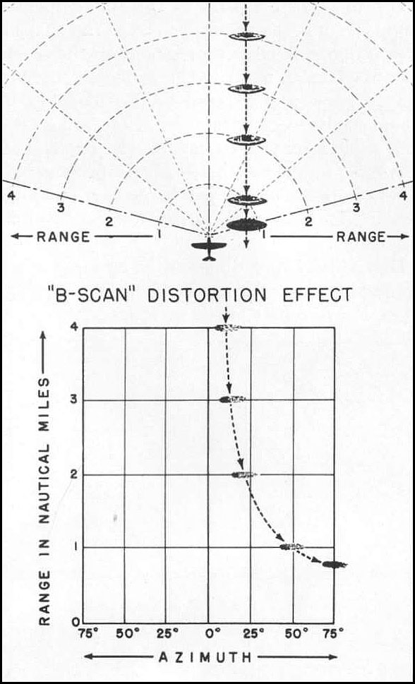
- B Scope - Common in Fighters - Azimuth and Range - More accurate Azimuth as target approaches
- C Scope - Azimuth and Elevation - Air Defence
- Plan Position Indicator - Azimuth as polar coordinate (in circle) and range - Map like
- Sector PPI - Azimuth as angle and range - Ground mapping radar
Non Cooperative Target Recognition (NCTR)The F-18 radar is a very modern radar using post receiver processing to establish as much data as possible. It includes a database of known harmonic parameters to be able to detect the Doppler from the spin of the target aircraft’s inlet compressor (or exhaust power turbine I think) blades and so can identify the aircraft.
|
|
|
|
Post by VBF-12 Gosling on Apr 12, 2019 11:21:55 GMT -5
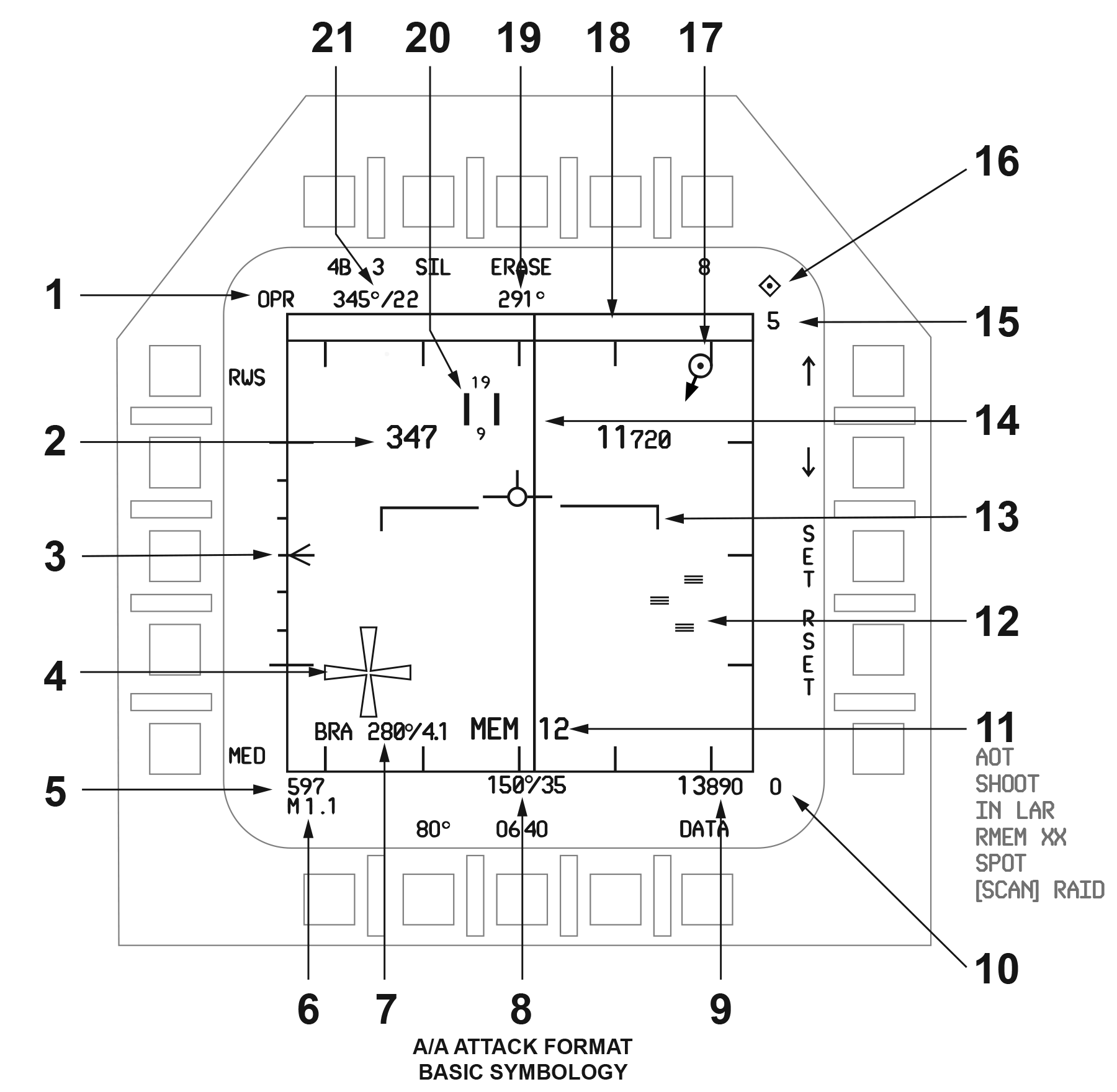
R03 - DDI SymbologyCaution: The DDI Diagrams are for the F-18E Super Hornet and so may be slightly in error. Also, not allo the feature display will have been implemented yet in the DCS current version. I will try to highlight differencesAircraft SetupOn Master Arm Panel: Master Arm Select ... ... ... ... ... ... ... ... ... ... Live A/A Master ... ... ... ... ... ... ... ... ... ... ... ... ... Select or On Stick: Weapon Select ... ... ... ... ... ... ... ... ... ... ... Select chosen A/A Weapon On the Sensor Control Panel (Right Thigh): Radar Control Knob ... ... ... ... ... ... ... ... ... OPR On DDI: Select Radar .. ... ... ... ... ... ... ... ... ... ... ... MENU (B3) / ATK RADAR (L3) - Right DDiI is preferable Attack Radar Basic SymbologyThe DDI Display of the Attack Radar has a plethora of information:  - Operating Status - The operating status options are:
- TEST - Self-Test or Initiated BIT (Built In Test)
- EMCON - Emissions Control (EMCON) selected on UFC
- DEGD - Due to a BIT failure or MUX Fail
- SIL - SILent operation
- STBY, OPR, or OFF from the power switch on the Sensor Control Panel
- Ownship Airspeed/Altitude (large) - Airspeed in knots & altitude in feet only if 5nm range scale!
- Antenna Elevation Scale / Caret - The antenna elevation from 0° in the center to ±60° at 10° and 30° increments. The caret moves vertically and is blanked if the Radar is tracking and the MSI L&S trackfile is nearing the gimbal limits of the antenna. It is pitch and roll stabilized to local horizon. In Scan modes it indicates the elevation of that scan bar. In tracking modes, the elevation caret denotes the actual antenna position relative to boresight.
- Maltese Cross - This is displayed by the Radar when it is not transmitting, i.e. when: EMCON, SIL, STBY, OFF or WonW.
- Ownship Airspeed - Knots
- Ownship Mach
- Ownship Bearing / Range to TDC Cursor - Whenever the TDC cursor is within the tactical area. Magnetic or true (as configured from the HSI>DATA>A/C format). 999 if range is greater than 999 nautical miles
- Ownship Bearing / Range to A2AWpt - If an A/A Waypoint ("Bullseye") is active. Displayed the same as Ownship BRA.
- Ownship Altitude - Altitude Above Mean Sea Level (AMSL). If RadAlt is selected on the HUD control panel, an “R” is displayed to the right unless it is invalid (over 5000ft), then barometric altitude is used and a flashing “B” is displayed
- Minimum Range Scale Setting
- High Priority Cues - These are generated by the MCs and are:
- AOT - Angle-Only Tracks (AOT) are those tracks for which the Radar cannot resolve a valid range
- RMEM - If the Radar is a contributor to the L&S trackfile and is reporting track extrapolated (predicted forward)
- SCAN RAID - If the Radar is operating in RAID from TWS, SCAN RAID is displayed
- SHOOT - If conditions for a successful launch of the selected weapon are met
- SPOT - This is displayed whenever the Radar is operating in Spotlight mode
- Raw Radar Hits / Echos - Displayed as small solid rectangles
- Velocity Vector / Horizon Bar - The velocity vector is fixed and the horizon line is moving to indicate the aircraft vertical flight path angle and roll attitude. Removed if DCLTR is selected. The horizon line flashes at its limit of +6°
- B-Sweep - Azimuth of the antenna as it sweeps
- Maximum Range Scale Setting - In nautical miles
- TDC Priority Cue - IF TDC is assigned to the Radar format, a diamond will appear
- A2A Waypoint (AAWP) - If the A2A Waypoint is selected the symbol ("bullseye") represents its position. The symbol is a circle with a pointer extending magnetic or true North. Only displayed on the RWS, TWS, and STT formats and is not displayed in the TWS expanded format. It is also displayed on the HSI and SA formats
- AOT Zone ("Dugout") - A trackfile without a valid range (jamming?), is an Angle-Only Track (AOT) and is displayed in the "Dugout" at the appropriate azimuth
- Ownship Heading
- Acquisition Cursor - Vertical parallel lines displayed at all times in RWS, VS and TWS modes when the TDC is on radar. Numbers above and below indicate the high and low altitude coverage of the current scan pattern for the range at which the cursor is displayed. The cursor is used for a variety of functions including, manual scan centering, Spotlight mode functions, trackfile designation and acquisition
- TDC Cursor Range / Bearing to A2AWpt - Not displayed if:
- Operating in VS, ACM condition, or STT modes
- TWS expanded (EXP) format
|
|
|
|
Post by VBF-12 Gosling on Apr 12, 2019 13:31:05 GMT -5
R04 - AIR / AIR MODESThere are three basic modes of search and one track operation as follows: Search Modes- Range While Search (RWS) - Provides detection of targets including high-closure rate, head-on attacks and low-closure rate, tail attacks. Unrestricted scan volume and scan centering control. Range versus azimuth B-Scan format with targets displayed as a synthetic blip scan ("brick") format. Trackfiles are generated and can also be displayed in RWS as Hostile Ambiguous Friendly Unknown (HAFU) symbols
- Velocity Search (VS) - This long range mode is for high-close rate targets. Presented on a velocity versus azimuth format
- Track While Scan (TWS) - Provides a multi-target detection and track capability. Tighter scan volumes and by auto scan centering control, allows for quicker updates. It maintains up to 12 track files which are provided to the MC for display on a range versus azimuth, B-Scan, format.
Automatic Acquisitions (AACQ)AACQ can be activated from any Search Mode and causes a FA as below: - Fast Acquisition (FA) - A FA is performed on a blip or a trackfile under the cursor when AACQ is commanded. This slaves the antenna to that position and commands acquisition on the target resulting in STT
- Bump Acquisition (BA) - To switch lock the BA causes radar to come out of a tracking mode and FA again but ignoring the previously tracked target for 10 secs
Air Combat Manoeuvring (ACM) Modes- Boresight Acquisition (BST) - Stabilised acquisition mode out to 10nm to locking up a visually acquired target ahead. Fly to get the target into the Boresight
- Gun Acquisition (GACQ) - Selected whenever the Gun is selected (Not in STT or another ACM mode). Radar will lock onto and track targets within the GACQ scan volume (approx HUD FoV) out to 5 nm
- Vertical Acquisition (VACQ) - Close (5 nm) range, narrow, tall, boresight stabilized Search suited to close-in detection of manoeuvring targets
- Wide Acquisition (WACQ) - Boresight or horizon stabilized scanning a wide azimuth area of sky with a small elevation differential out to 10nm
Single Target Track (STT)Single target track is the radar locked to an individual track and passes intercept information to the weapon to assess release parameters. This provides the information to the HUD to give the appropriate data for engagement.
|
|
|
|
Post by VBF-12 Gosling on Apr 13, 2019 18:33:46 GMT -5
R05 - DISPLAY INTERPRETATIONContact DisplayContacts detected by the radar but before being displayed they are processed by the MC. What you actually see is a synthetic “brick”. These are equal and so object size is not represented, they are either present or not. Scan BarsTo cover sufficient volume of sky with sufficient radiated power the radar cannot cover the whole space in one sweep. It has to scan in bars working vertically upwards from the bottom. These sweeps will thus miss detecting targets outside of the current bar until it sweeps that area again. The number of bars aND how often they are swept can be controlled manually. B-Scan Azimuth DisplayThe radar display contacts using a B-Scan format. This means a contact that is closing the aircraft on a constant bearing will come directly down the screen. Thus, the base of the display is able to show close contacts with much more azimuth clarity than a “pie segment” type of display. However, the B-Scan display distorts a contact that is flying a reciprocal course and will pass to one side of the aircraft. In this event the B-Scan will display the contact curving away to one side.  B-Scan Range Display B-Scan Range DisplayThe power transmitted from the radar remains the same whatever the range scale selected. The scales vary from 160nm down to 5nm. Some of the symbology changes when within the 5nm scale. Also, some of the Acquisition modes force the range scale to 10nm or 5nm.
|
|
|
|
Post by VBF-12 Gosling on Apr 14, 2019 4:54:17 GMT -5
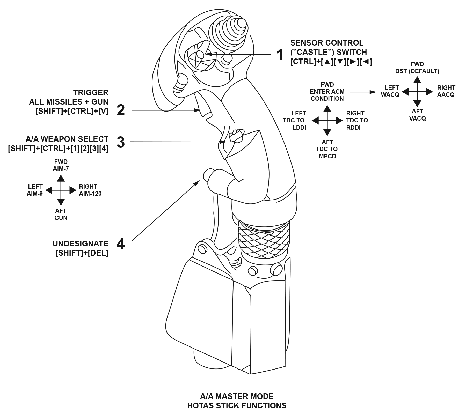
R06 - CONTROLS AND INTERACTIONChaps - Standby on this page. Firstly I have to interpret the Super Hornet control methodology clearly and tehn test on teh F-18C and current mod state to confirm it does the same thing...!!!The radar is designed to be controlled without removing the hands from stick and throttle. However, many of the more deep options are also available through the Option Buttons of the DDI. Stick ControlsThe stick controls adjust the radar depending upon the weapon selected.  - Sensor Control
A four position momentary, return-to-center switch which has many functions. They are defined by the allocation of the TDC and the state of the radar. Each click has a sequential action as follows:- Select FWD ▲ -
- First click - Commands Radar into Boresight Acquisition (BST) mode
- Second click - Radar is already tracking (STT) = Commands Bump Acquisition
- Select LEFT ◄ -
- First Click -
- LDDI format not TDC capable - LDDI to Stores
- LDDI format is TDC Capable - TDC to LDDI
- LDDI format is SA or HSI page - LDDI switched between those pages
- LDDI format is Attack Radar - Command ACM with FA mode and track if possible
- Second Click -
- LDDI Radar is tracking - Commands WACQ and start tracking if possible
- Select RIGHT ► -
- First Click -
- RDDI format not TDC capable - RDDI to A/A Radar
- RDDI format is TDC Capable - TDC to RDDI
- Second Click -
- RDDI is A/A Radar - Command ACM in AACQ (or FA if cursor over Tgt) and track if possible
- Third Click -
- RDDI is Radar and tracking - Commands GACQ
- Select AFT ▼ -
- In ACM Mode (any of BST, GACQ, VACQ, WACQ) - Commands VACQ
- Trigger - In A/A Master Mode, the trigger is used to fire all missiles and the Gun
- A/A Weapon Select -
- On deck - Commands A/A Master Mode
- Airborne - Selects air weapon as follows:
- FWD ▲ - AIM-7 - Initializes the Radar and displays for the AIM-7. Next click = next AIM-7
- LEFT ◄ - AIM-9 - Initializes the Radar and displays for the AIM-9. Next click = next AIM-9
- RIGHT ► - AIM-120 - Initializes the Radar and displays for the AIM-120. Next click = next AIM-120
- AFT ▼ - Gun - , Initializes the Radar into ACM and GACQ and displays for A/A gunnery
- Undesignate:
- On deck:
- Toggle between LO and HI nosewheel steering
- Airborne and in the A/A Master Mode:
- Commands the Radar to search or
- Create or step the L&S trackfile designation to another track
- In ACM Mode (any of BST, GACQ, VACQ, WACQ)[)
- Selected weapon is not Gun:
- Commanded to Search Mode (most recent of RWS, VS, TWS
- Selected weapon is Gun:
- Exits Radar ACM mode
- Not in ACM (not in any of BST, GACQ, VACQ, WACQ)[:
- Commands search if the Radar is operating in one of:
- Auto Acq (AACQ)
- STT
- Acquisition (Manual or an ACM mode)
- FLOOD
- RWS/VS Spotlight mode.
- Launch & Steering (L&S) Target functions in priority:
- Making the highest ranked MSI trackfile the L&S target if no L&S exists
- Swapping the L&S and DT2 designations if both already exist
- Stepping the L&S designation to another MSI trackfile when an L&S exists without a DT2
|
|