|
|
Post by VBF-12 Gosling on Nov 23, 2018 11:39:28 GMT -5
Guys
An update for the F-18 which I beleive arrived last Wednesday....
I’ll try to work out how it works...
Edit:
I was a bit early with this. It was in Beta... However, it has just been added during the recent update (14 Dec 18).
|
|
|
|
Post by VBF-12 Sluggo on Dec 5, 2018 19:53:45 GMT -5
I am not sure it was released yet. I see it on grim reapers but have not been able to start it.
|
|
|
|
Post by VBF-12 Gosling on Dec 6, 2018 11:05:40 GMT -5
Really, I havent had the opportunity to try.
|
|
|
|
Post by VBF-12 Gosling on Dec 20, 2018 13:48:05 GMT -5
It has now  .... |
|
|
|
Post by VBF-12 Sluggo on Dec 21, 2018 16:32:58 GMT -5
Got it finally. Nice option. I still don’t think I am using the radars correctly, but more practice should help.
|
|
|
|
Post by VBF-12 Gosling on Dec 21, 2018 16:44:01 GMT -5
Did you see the explaination on how the radar works on a Youtube....
I think I posted it.
I think we need to be very used to the controls to be able to switch between the modes. It will take practice
|
|
|
|
Post by VBF-12 Gosling on Dec 22, 2018 8:55:26 GMT -5
Okay, I have got home and have a chance to look at the helmet mounted display.
Firstly, I am going to give you a list of abbreviations and their meanings as I think this will dispel alot of the "mystique" around this equipment.
JHMCS - Joint Helmet Mounted Cueing System - The whole system including, the helmet mounted displays, electronics unit, HMD/AHMD off/brightness knobs, aft cockpit Boresight Reference Unit (BRU), cockpit units, magnetic transmitter units, and seat position sensors in each cockpit
HMD - Helmet Mounted Display - The equipment attached to your helmet. Each HMD consists
of the helmet, Helmet Display Unit (HDU), Helmet-Vehicle Interface (HVI), and a universal connector which connects the HDU to the helmet
HDU - Helmet Display Unit, includes a CRT, Magnetic Receiver Unit (MRU),
camera, auto-brightness circuitry, uplook reticles, and visor
BRU - Boresight Reference Unit - Allows alignment of the helmet to the aircraft - For aft cockpit only so not for us
HVI - Helmet Vehicle Interface - Two cable parts and three connectors, which connect the helmet to the aircraft. Helmet Release Connector (HRC), helmet to upper HVI cable. Quick Disconnect Connector (QDC) between Upper and Lower HVI. QDC to lower HVI to In-line Release COnnector (IRC) to the aircraft.
HRC - Helmet Release Connector - Connect HVI cable to the helmet
QDC - Quick Disconnect Connector - Seated in a Quick Release Mounting Bracket attached to the seat harness. Allows separaion on ejection.
IRC - Inline Release Connector - Connects HVI cable to aircraft. Backup if the QDC fails and will break at 80-120 pounds pull.
CRT - Cathode Ray Tube - Inside the HMD and projects the display for you to see
EU - Electronics Unit - contains the main system CPU, LOS module, graphics processor/display drive, and low voltage power supply.
CPU - Computer Processor Unit - controls system bus interfacing, display list generation, BIT, and other system functions.
BIT - Built In Test - There are a number of these - see below
LOS - Line of Sight module - calculates helmet LOS
MC - Main aircraft computer - interface with the EU via the MUX
MUX - Multiplex - Computer interface units
CU - Cockpit Unit - ontains the system high voltage power supply for helmet display
MTU - Magnetic Transmitter Unit - used to generate a magnetic field used to determine HMD/AHMD position/orientation - 15 to 20 mins warmup!!! I doubt this is implemented - must test this out...
MRU - Magnetic Receiver Unit - receives the MTU magnetic field and send the received signal to the EU - It is above your left shoulder
SPS.- Seat Position Sensor - The seat affects the magnetic field in the cockpit so this sensor knows where the seat is to compensate
HMD OFF/BRT knob - On Spin Recovery Panel - Basic power to the HMD
VTR - Video recording of helmet display - on CVRS Panel
Built In Tests:
SBIT - Start-up Built In Test - When the HMD system is turned on, SBIT starts automatically and the internal software is loaded in the EU. SBIT cannot be stopped until it is completed. PBIT GO or DEGD, as appropriate, is displayed when SBIT is completed.
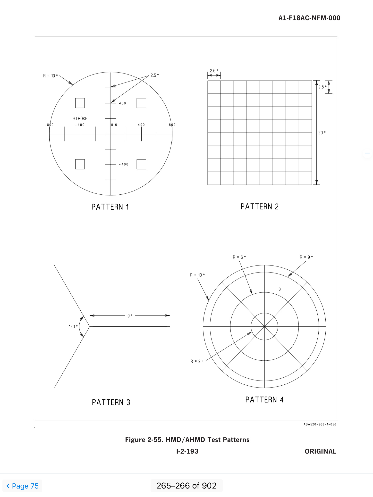
IBIT - Initiated Built In Test - performed when the HMD Right Top push button option is selected on the DISPLAYS BIT sublevel display - four test patterns.
STOP - Top 5 Push Button - Stops IBIT patterns
more to follow...
|
|
|
|
Post by VBF-12 Gosling on Dec 22, 2018 10:12:44 GMT -5
Start Up and Align ProceedurePower Up: The front cockpit HMD OFF/BRT knob is located on the Spin Recovery panel. This knob removes and applies power to the HMD, and adjusts HMD display brightness. Basically, I think it sorts itself out and the following is not needed but this is how it is supposed to be done. Warm Up: The MTU is supposed to take about 15-20 minutes to warm up. I suspect this delay will be bypassed in the game, however I have yet to test this. Aligning the HMD before it is warmed up can cause small boresight errors.
Alignment Stage 1 - Course Align: It seems the Course Align function has yet to be implemented. 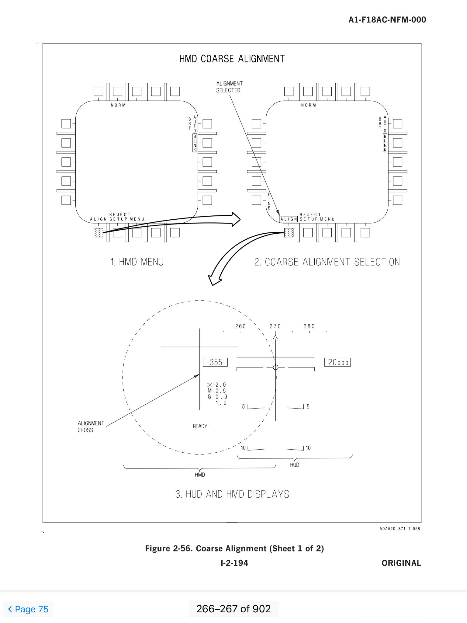 Alignment Stage 2 - Fine Align: It seems the Fine Align function has yet to be implemented. 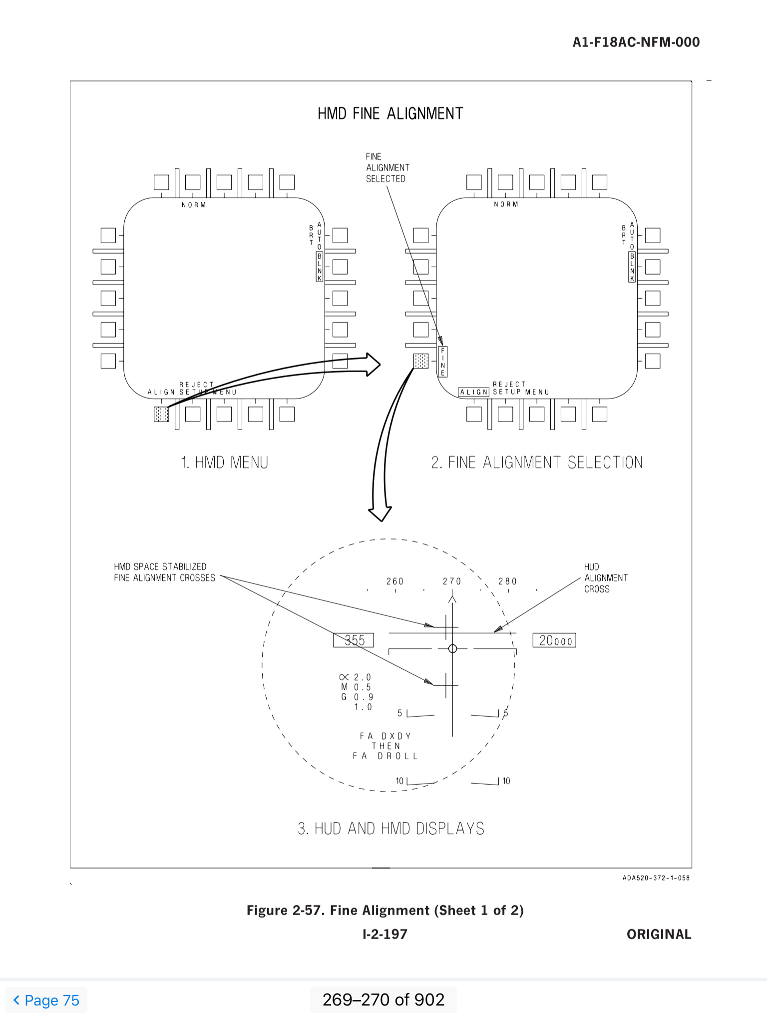
|
|
|
|
Post by VBF-12 Gosling on Dec 22, 2018 10:13:06 GMT -5
HMD - SymbologyThe HMD layout essentially replicates the HUD layout. Window locations, format, and occlusion level on the HMD are as identical to the HUD locations, format, and occlusion level as practical. Some of the symbology on the HUD is either not required on the HMD or would be disorienting if the information was presented. Aircraft Attitude Data - Some HUD data only provides the pilot usable information when presented along the aircraft boresight. HMD data is not always presented along the aircraft boresight. For this reason the following are NOT displayed on the HMD: - Pitch Ladder
- Horizon Bar
- Water Line indicator
- Velocity Vector
|
|
|
|
Post by VBF-12 Gosling on Dec 22, 2018 10:13:49 GMT -5
HMD - Built In Test Functionality
SBIT Test:When the HMD system is turned on, Start-Up Built In Test (SBIT) starts automatically and the internal software is loaded in the EU. SBIT cannot be stopped until it is completed. PBIT GO or DEGD, as appropriate, is displayed when SBIT is completed. This is on the BIT / DISPLAYS page. IBIT Test:Initiated Built In Test is performed when the HMD (R1) option is selected on the BIT / DISPLAYS page. IN TEST flashes on the HMD, and an initiated BIT is performed. When IBIT is complete, a series of four test patterns, which are automatically changed each second, are displayed on the HMD/AHMD. - On a DDI select MENU (B3) to get the SUPT menu
- Select BIT (T3)
- Select DISPLAYS(R1)
- The HMD will read PBIT GO - Which means it has completed its SBIT and is ready to conduct the IBIT
- Select HMD (R1)
- The HMD will display IN TEST and then display the 4 test patterns in 1 second steps.
- Select STOP (T5)
- In the list of DISPLAYS the HMD should read GO
 Status Messages: Status Messages:Refer to the following for status messages and associated descriptions: | STATUS MESSAGE | DESCRIPTION | | MUX FAIL | Equipment ready discrete is high but the EU is not communicating on either MUX bus to the MC | | OT RDY | Equipment ready discrete is low and the EU is not communicating on either MUX bus to the MC | | IN TEST | Initiated BIT in progress | | RESTRT | Re-initiate BIT, EU did not respond to the IBIT command or IBIT did not complete within 30 seconds | | DEGD | EU has detected a failure which degrades system performance | | OVRHT | EU has reported a component as overheated | | DEGD+OVRHT | EU has detected a failure and EU has reported a component as overheated | | GO | EU responded with no failures | | OP GO | EU has detected a failure which does not degrade system performance | | PBIT GO | EU responded with no failures prior to performing IBIT |
|
|
|
|
Post by VBF-12 Gosling on Dec 22, 2018 13:16:32 GMT -5
HMD - Reject FunctionalityThe HMD can have its symbology decluttered. There are four stages: NORM - Normal full symbology REJ 1 - Reject 1 declutter REJ 2 - Reject 2 declutter BLNK - Blanks ths HMD when facing the HUD, except for the HMD pitch symbol. The HMD displays when looking off the aircraft axis. Selection of symbology displayed during declutter:The content of each declutter can be adjusted. - On a DDI select MENU (B3) to get the SUPT menu
- Select HMD (L3)
- Select REJECT SETUP (B2)
- The following will be displayed as the default setup:
| ALTITUDE | ON | WINDOW 1 | 1 | | AIRSPEED | ON | WINDOW 2 | 2 | | BARO/RADALT | ON | WINDOW 3 | 2 | | BARO PRESS | ON | WINDOW 4 | 2 | | VSI | ON | WINDOW 5 | 2 | | ALPHA | ON | WINDOW 6 | 2 | | NIRD CIRCLE | ON | WINDOW 7 | 2 | | MSL FOR | ON | WINDOW 8 | 2 | | SP/AMR FOV | ON | WINDOW 9 | 2 | | EW | ON | WINDOW 10 | 2 | | HMD HEADING | 2 | ALT_ASPD_BOX | 1 | | HMD ELEV | 2 | CLIMO_ASPD | 1 | | A/C HEADING | 2 | MACH | 1 | | TIME WINDOW | 2 | G | 1 | | | MAX G | 1 | | MEMBERS | 2 | | | | CLOSEST FRND | 1 | DONORS | 2 | | TUCD TRACK | 1 | OTHERS | 2 | | | MIDS INFO | 1 |
- Use the Left Arrowe (T1) to select the Left Column and the Right Arrow (T2) to select the Right Column.
- Use the UP Arrow (L1) and Down Arrow (L2) to select (box) the required paramter.
- Use the ON (L3), 1 (L4) or 2 (L5) to select the rejection level for the boxed parameter.
Finish REJECT SETUP:Implement REJECT- On a DDI select MENU (B3) to teh SUPT menu
- Select HMD (L3)
- Select NORM (T2) to implement REJ 1
- Select REJ 1 (T2) to implement REJ 2
- Select REJ 2 (T2) to implement MORM
- Select BLNK (R1) to implement Blank (boxed)
- Re-select BLNK (r12) to unbox BLNK and reinstate previously selcted MORM/REJ 1/REJ 2.
|
|
|
|
Post by VBF-12 Sluggo on Dec 31, 2018 15:10:33 GMT -5
Fantastic!
|
|
|
|
Post by VBF-12 Gosling on Feb 5, 2019 0:00:45 GMT -5
New video showing how to lock targets with the helmet mounted display:
|
|


 ....
....