Post by VBF-12 Gosling on Jul 22, 2018 12:34:10 GMT -5
We have to look at this sometime....!!! It’s a really big thing and I’m going to take it in chunks....
I have referenced each part to its page in the F-18 Aircraft Manual: F-18-ABCD-000 to allow you to read the manual in tiny chunks and slowly get to grips with it. It has a lot of detail straight away and I feel that hinders the reader from getting the overview of teh system. Hence this thread. Hopefully, this gives the overview and the linked pages gives the detail. This does NOT appear to work on mobile platforms (iPad, iPhone etc). Just scroll to the page
Here are the posts on this subject:
A01 - Avionic Systems Overview
A02 - Modes, Controls and Displays
A03 - Digital Display Indicators (DDI)
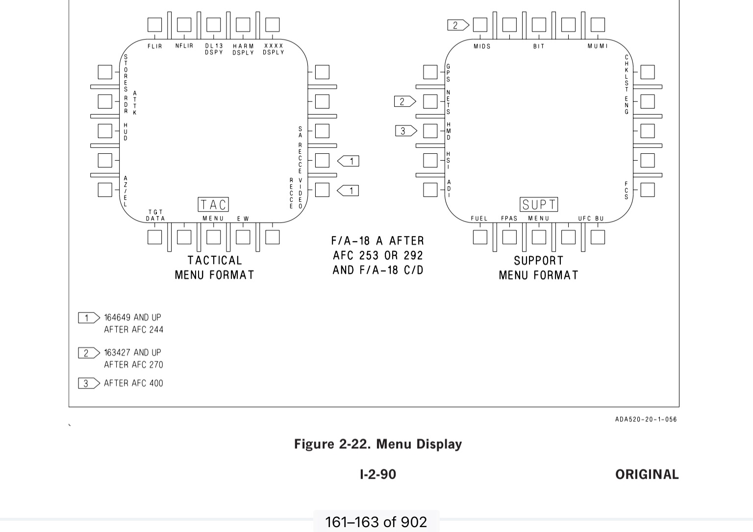
A04 - DDI Menus
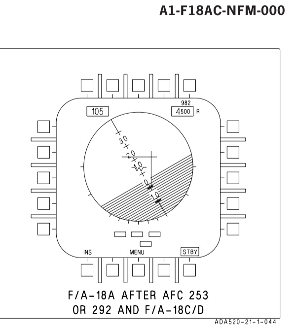
A05 - Electronic Attitude Display Indicator (EADI)
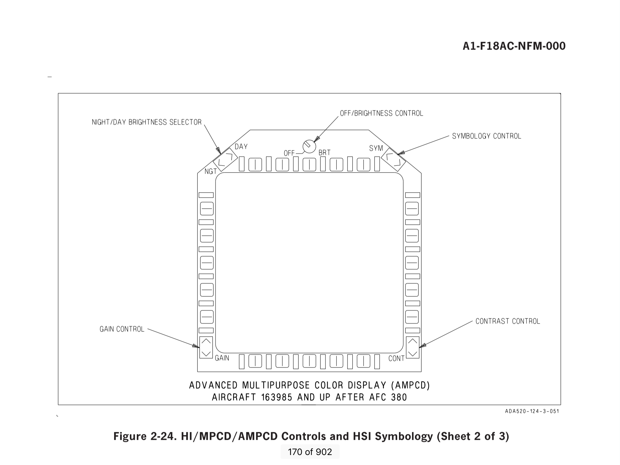
A06 - Advanced Multipurpose Colour Display (AMPCD)
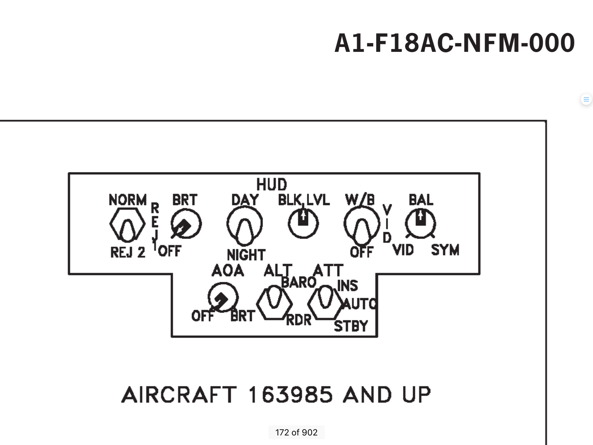
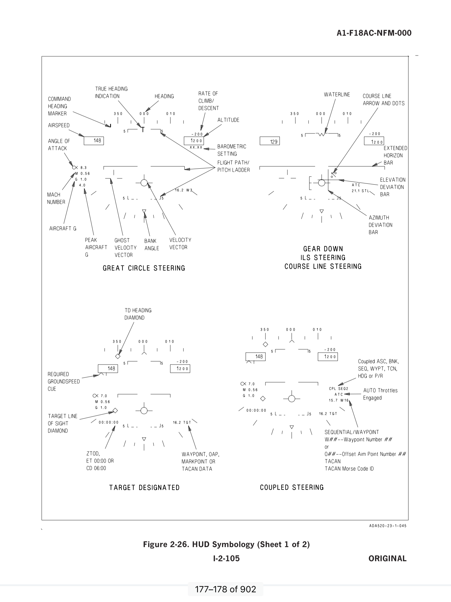
A07 - Head Up Display
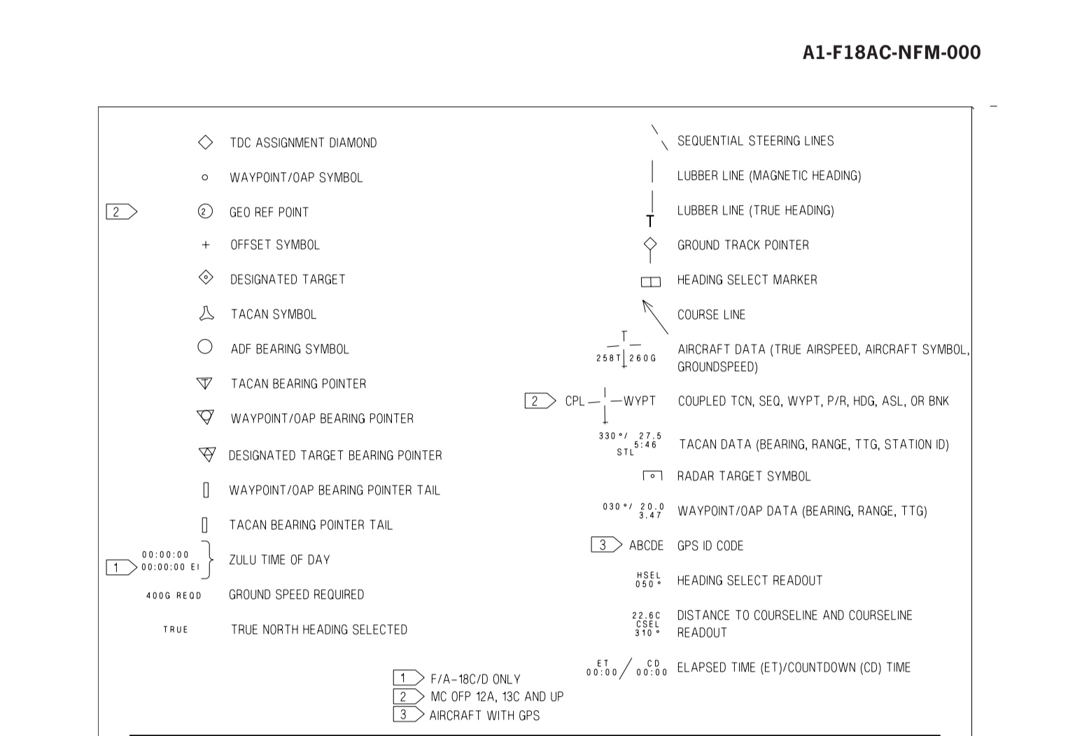
A08 - DDI & AMPCD Symbology
A09 - HUD Symbology
A01 - OVERVIEW
The first sentence in the manual says it all really....
2.13 AVIONICS SUBSYSTEM - Reference: F-18-ABCD-000 - Para 2.13 on page 148
The avionics subsystem combines the integration and automation needed for one-man operability with the redundancy required to ensure flight safety and mission success.
So let’s build the system up....
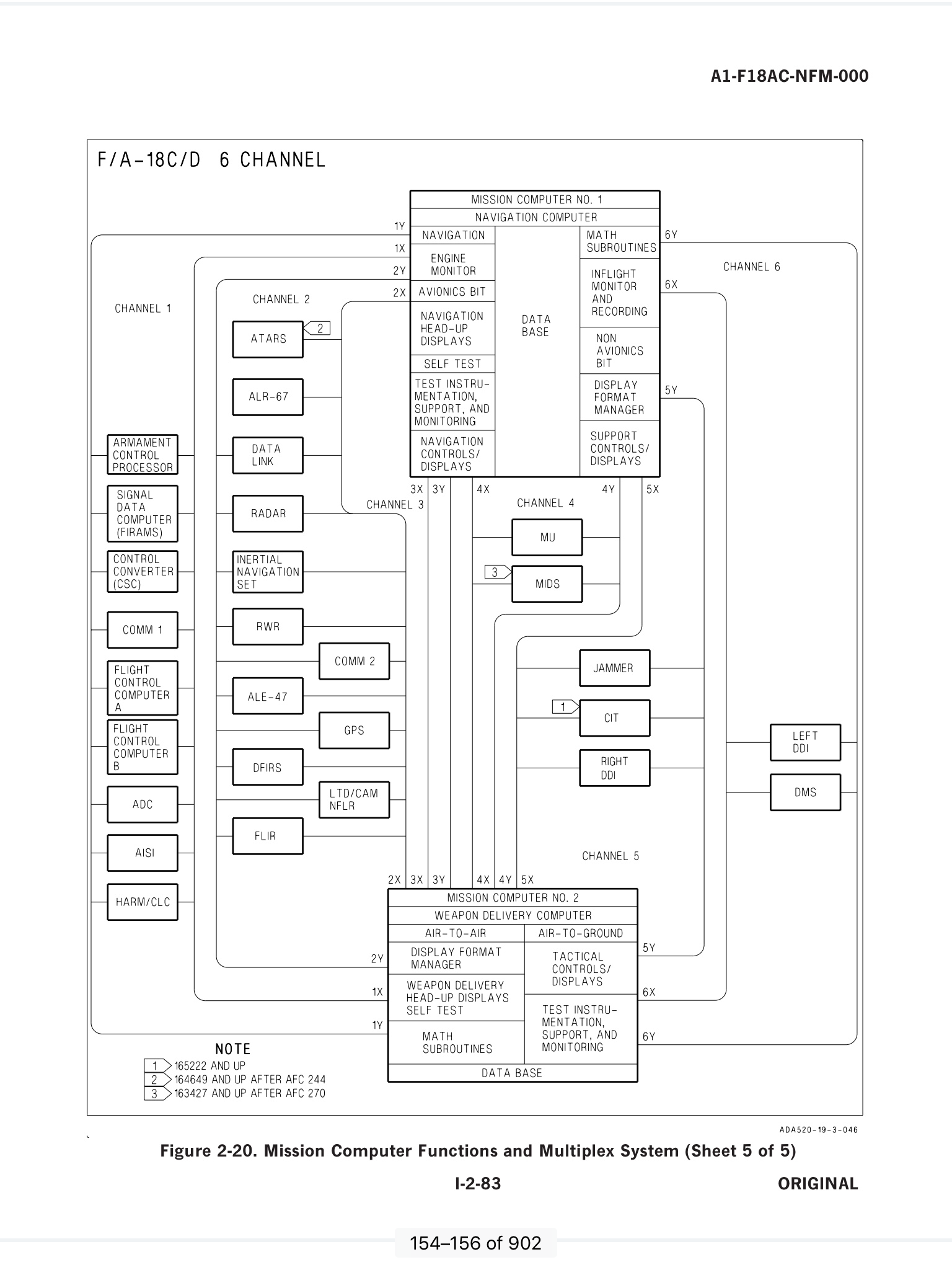
Mission Computers - Reference: F-18-ABCD-000 - Para 2.13.1 on page 148
Two primary mission computers that back each other up as they are interconnected by a databus, called a MUX (Multiplex). It’s probably a 1553 databus. This also connects all the avionic equipment to the computers so that they have the data to present to the pilot.
Mission Computer 1 = Navigation Computer
Mission Computer 2 = Weapon Delivery Computer
Like the hydraulics, the system is split up into multiple channels. Our aircraft has 6:
This image is linked to the Manual.
Each piece of equipment is connected via a channel twice, X and Y, for redundancy.
Each MC is compartmentalised, which is more conceptual than physical. It allows the software to conduct functions without other software routines compromising them. Take a look at the diagram above:
Channel 1 - Equipment
Channel 2 - Equipment
Channel 3 interconnects the two MCs only
Channel 4 - Equipment
Channel 5 - Equipment
Channel 6 - Equipment
I have referenced each part to its page in the F-18 Aircraft Manual: F-18-ABCD-000 to allow you to read the manual in tiny chunks and slowly get to grips with it. It has a lot of detail straight away and I feel that hinders the reader from getting the overview of teh system. Hence this thread. Hopefully, this gives the overview and the linked pages gives the detail. This does NOT appear to work on mobile platforms (iPad, iPhone etc). Just scroll to the page
Here are the posts on this subject:
A01 - Avionic Systems Overview
A02 - Modes, Controls and Displays
A03 - Digital Display Indicators (DDI)
A04 - DDI Menus
A05 - Electronic Attitude Display Indicator (EADI)
A06 - Advanced Multipurpose Colour Display (AMPCD)
A07 - Head Up Display
A08 - DDI & AMPCD Symbology
A09 - HUD Symbology
A01 - OVERVIEW
The first sentence in the manual says it all really....
2.13 AVIONICS SUBSYSTEM - Reference: F-18-ABCD-000 - Para 2.13 on page 148
The avionics subsystem combines the integration and automation needed for one-man operability with the redundancy required to ensure flight safety and mission success.
So let’s build the system up....
Mission Computers - Reference: F-18-ABCD-000 - Para 2.13.1 on page 148
Two primary mission computers that back each other up as they are interconnected by a databus, called a MUX (Multiplex). It’s probably a 1553 databus. This also connects all the avionic equipment to the computers so that they have the data to present to the pilot.
Mission Computer 1 = Navigation Computer
- Navigation
- LControl/Display Management
- Built-in-Test (BIT) management
- Status Monitoring
- MC2 Backup/li]
Mission Computer 2 = Weapon Delivery Computer
- Air-to-Air
- Air-to-Ground
- Tactical Control/Display
- MC1 Backup
Like the hydraulics, the system is split up into multiple channels. Our aircraft has 6:
This image is linked to the Manual.
Each piece of equipment is connected via a channel twice, X and Y, for redundancy.
Each MC is compartmentalised, which is more conceptual than physical. It allows the software to conduct functions without other software routines compromising them. Take a look at the diagram above:
Channel 1 - Equipment
- Armament Control Processor - Stores Management
- Signal Data Computer A
- Comm 1. Radio Control
- Flight Control Computer A
- Flight Control Computer B
- Air Data Computer - Gathers info form the sensors like the Pitot and Static
- AISI - I have yet to find out what this is!!! There appears to be no references to this in the manual...!
- HARM/CLC - Highspeed Anti-Radiation Missile Command Launch Computer
Channel 2 - Equipment
- ATARS - Advanced Tactical Air Reconnaissance System
- ALR-67 - Part of the Radar Warning Receiver (RWR)
- Data Link - To the ship
- Radar
- Inertial Navigation Set - Ring laser gyros
- RWR - Radart Warning Receiver - Part of Electronic Warfare (EW) equipment
- ALE-47 - Chaff and Flare dispenser
- DFIRS - Deployable Flight Incident Recorder System - Deploys on ejection
- FLIR - Forward Looking Infrared Camera
- Comm 2 - Radio
- GPS - Global Positioning System - The US GNSS
- LTD - Laser Detector Tracker/Camera, NFLR - Navigation Forward Looking Infrared
Channel 3 interconnects the two MCs only
Channel 4 - Equipment
- MU - Memory Unit
- MIDS - Multi Information Distribution System - For Radios and TACAN
Channel 5 - Equipment
- Jammer - The ALQ-165 - Airborne Self Protectin Jammer (ASPJ)
- CIT - Conbined Interrogator/Trasponder
- Right DDI - Digital Display Indicator
Channel 6 - Equipment
- Left DDI - Digital Display Indicatior
- DMS - Digital Map System