Post by VBF-12 Gosling on Jul 18, 2018 5:01:46 GMT -5
Chaps
This is no where near as bad as it looks. It’s really quite simple...
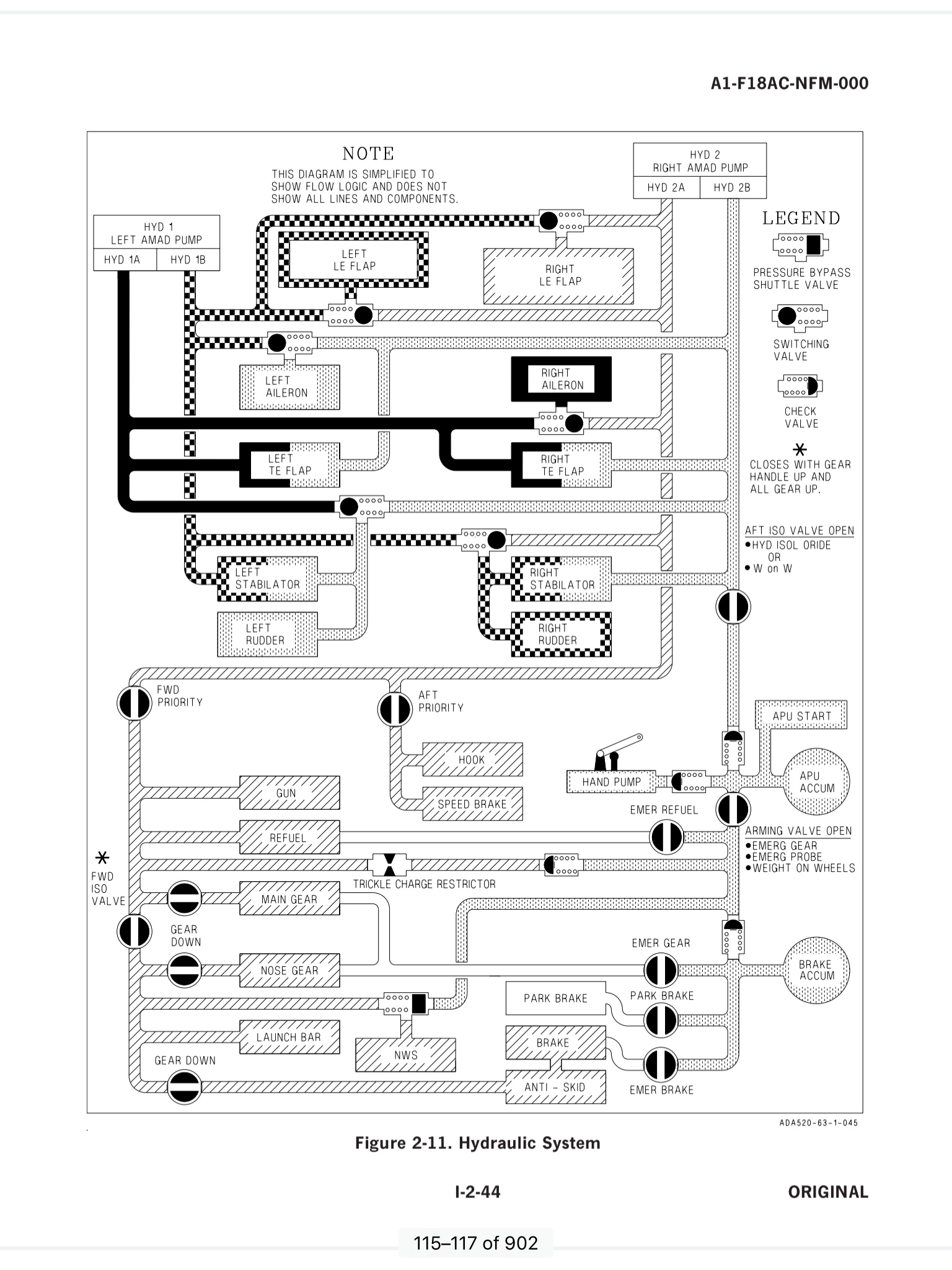
There are TWO main system (Hyd1, Hyd2) each with TWO channels (A, B) at the top left and top right of the diagram.
The diagram is in TWO half’s. Top is Flight Control Surfaces, bottom is ancillary systems. Just follow the lines from the items back to the Hydraulic pumps at the top. From the top:
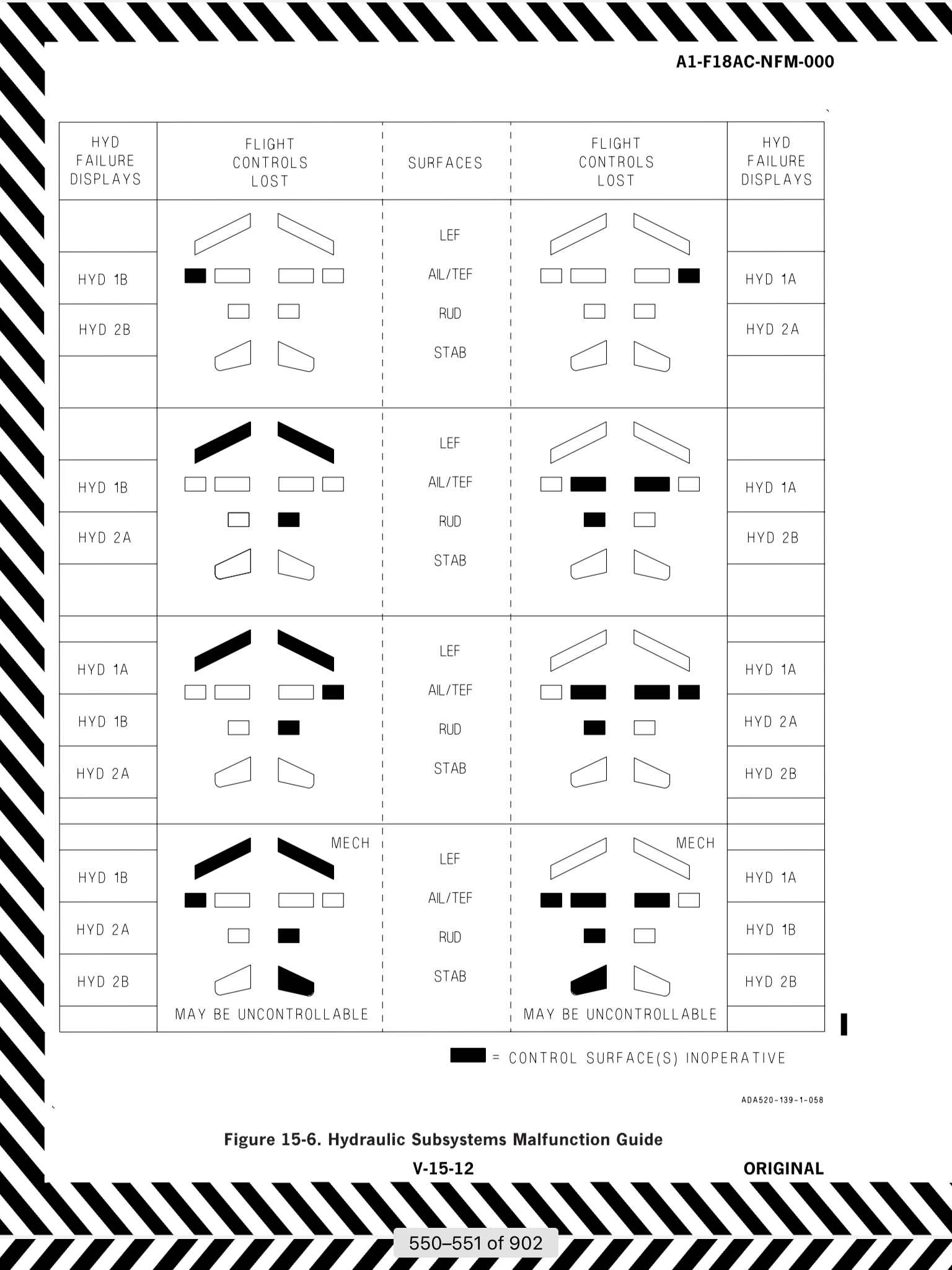
Leading Edge Flaps (LEF) - Left fed by Hyd1B, backup if pressure in 1B lost = Hyd2A
Leading Edge Flaps (LEF) - Right fed by Hyd2A, Backup if pressure in 2A lost = Hyd1B
Aileron - Left fed by Hyd2B, Backup Hyd1B
Aileron - Right fed by Hyd1A, Backup Hyd2A
Trailing Edge Flap (TEF) - Left fed by both Hyd1A & Hyd2B in tandem. Internal configuration in the jack will avoid hydraulic lock in the case of a failure of either system.
Trailing Edge Flap (TEF) - Right fed by both Hyd1A & Hyd2B in tandem. Internal configuration in the jack will avoid hydraulic lock in the case of a failure of either system.
Stabilator - Left fed by the higher pressure system of Hyd1A or Hyd2B AND higher of Hyd1B or Hyd2A, in tandem. So TWO of any of the FOUR systems.
Stabilator - Right fed by the higher pressure system of Hyd1B or Hyd2A AND higher of Hyd1A or Hyd2B, in tandem. So TWO of any of the FOUR systems.
Rudder - Left fed by higher of Hyd2B or Hyd1A
Rudder - Left fed by higher of Hyd1B or Hyd2A
Now the bottom half:
Pretty much the whole system is driven by Hyd2A with some systems backed up by Hyd2B if selected.
Hook - Hyd2A only
Speed Brake - Hyd2A only
- Can be selected both OFF
Gun - Hyd2A only
Refuel Probe - Hyd2A. Backup Hyd2B if selected
Main Landing Gear - Hyd2A when selected down
Nose Landing Gear - Hyd2A when selected down
- Landing Gear Backup = Higher pressure of Hyd2B or Brake Accumulator if selected
Launch Bar - Hyd2A only
Nose Wheel Steering - Higher of Hyd2A or Hyd2B
Parking Brake - Hyd2B by selection
Brake - Hyd2A via Anti-Skid. Backup by higher of Hyd2B or Brake Accumulator but without Anti-Skid
Anti-Skid - Hyd2A but only when the gear is down
During start, there is a APU Pump and accumulator which charges the Brake Accumulator and powers the Brakes and Nose wheel steering before engine start.
Finally, for the Chockheads there is a Hand Pump that also charges the brake accumulator. This allows recharge of the brakes if the aircraft is standing for long periods. Onboard it would be used if respotting the aircraft on deck.
The only part I am struggling to understand is the purpose of the Trickle Charge (Centre of bottom half of diagram) link between the Hyd1A and Brake Accumulator. Seem to me a leak in and around the brake accumulator would lead to a slow leak of the whole Hyd2 system!!!! I cant see the reason behind this connection
See, not so bad....
This is no where near as bad as it looks. It’s really quite simple...
There are TWO main system (Hyd1, Hyd2) each with TWO channels (A, B) at the top left and top right of the diagram.
The diagram is in TWO half’s. Top is Flight Control Surfaces, bottom is ancillary systems. Just follow the lines from the items back to the Hydraulic pumps at the top. From the top:
Leading Edge Flaps (LEF) - Left fed by Hyd1B, backup if pressure in 1B lost = Hyd2A
Leading Edge Flaps (LEF) - Right fed by Hyd2A, Backup if pressure in 2A lost = Hyd1B
Aileron - Left fed by Hyd2B, Backup Hyd1B
Aileron - Right fed by Hyd1A, Backup Hyd2A
Trailing Edge Flap (TEF) - Left fed by both Hyd1A & Hyd2B in tandem. Internal configuration in the jack will avoid hydraulic lock in the case of a failure of either system.
Trailing Edge Flap (TEF) - Right fed by both Hyd1A & Hyd2B in tandem. Internal configuration in the jack will avoid hydraulic lock in the case of a failure of either system.
Stabilator - Left fed by the higher pressure system of Hyd1A or Hyd2B AND higher of Hyd1B or Hyd2A, in tandem. So TWO of any of the FOUR systems.
Stabilator - Right fed by the higher pressure system of Hyd1B or Hyd2A AND higher of Hyd1A or Hyd2B, in tandem. So TWO of any of the FOUR systems.
Rudder - Left fed by higher of Hyd2B or Hyd1A
Rudder - Left fed by higher of Hyd1B or Hyd2A
Now the bottom half:
Pretty much the whole system is driven by Hyd2A with some systems backed up by Hyd2B if selected.
Hook - Hyd2A only
Speed Brake - Hyd2A only
- Can be selected both OFF
Gun - Hyd2A only
Refuel Probe - Hyd2A. Backup Hyd2B if selected
Main Landing Gear - Hyd2A when selected down
Nose Landing Gear - Hyd2A when selected down
- Landing Gear Backup = Higher pressure of Hyd2B or Brake Accumulator if selected
Launch Bar - Hyd2A only
Nose Wheel Steering - Higher of Hyd2A or Hyd2B
Parking Brake - Hyd2B by selection
Brake - Hyd2A via Anti-Skid. Backup by higher of Hyd2B or Brake Accumulator but without Anti-Skid
Anti-Skid - Hyd2A but only when the gear is down
During start, there is a APU Pump and accumulator which charges the Brake Accumulator and powers the Brakes and Nose wheel steering before engine start.
Finally, for the Chockheads there is a Hand Pump that also charges the brake accumulator. This allows recharge of the brakes if the aircraft is standing for long periods. Onboard it would be used if respotting the aircraft on deck.
The only part I am struggling to understand is the purpose of the Trickle Charge (Centre of bottom half of diagram) link between the Hyd1A and Brake Accumulator. Seem to me a leak in and around the brake accumulator would lead to a slow leak of the whole Hyd2 system!!!! I cant see the reason behind this connection
See, not so bad....